This tutorial installment is: Unregulated Power Supplies. This topic answers the following questions:
- What are unregulated power supplies?
- What are the basic types of unregulated power supplies?
- What are the advantages and disadvantages of unregulated power supplies?
To view a different topic, go to the Power Supply Tutorial table of contents.
Last topic: The Achille’s Heel of Electronics Products
Next topic: Linear Power Supplies
Unregulated Power Supplies Introduction
This article about the unregulated supply is the third in a series about basic power supply topics for the benefit of the OEM. The power supply is not a source of energy but, rather is an electronic circuit thoughtfully designed to change energy from the form of an available source to the form required by the load. In effect, the power supply is an interface matching the source to the load. The power supply will always obey the Law of Conservation of Energy.
An unregulated power supply is a simple power supply whose output is a function of the input source voltage, output load, and ambient temperature. There is no circuitry added to regulate the output, compensating for these effects.
Types of Unregulated Power Supplies
There are three types of unregulated power supplies which can change AC voltage to DC:
- 1. Half-wave rectified
- 2. Full-wave center tap rectified
- 3. Full-wave bridge rectified
Half-Wave Rectified Supply
This supply uses a transformer with a single secondary winding followed by a single, uncontrolled, rectifying diode. The rectifier conducts only during the positive half cycle. This circuit has the minimum parts count. However, the transformer is utilized only during the positive half cycle, resulting in greater RMS heating for a given average current output when compared to the full wave bridge. Due to the half wave rectification, the output capacitor must supply the load current for almost the complete cycle without a recharge, resulting in a large output voltage ripple. The greater the load, the greater is the ripple. If the capacitor were to be sized larger to lessen the ripple, the capacitor RMS current would greatly increase and RMS heating increases according to the square of the current.
Therefore, this circuit is only practical at very low power levels. The rectifier diode must be rated for at least twice the maximum output voltage and the circuit experiences one diode drop of voltage and dissipation loss.
Half-Wave Rectified Supply
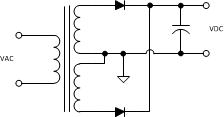
Full-Wave Center Tap Rectified Supply
The full-wave center tap supply has a transformer with two equal turn count secondary windings, each one followed by a single uncontrolled, rectifying diode with the other end of the diodes tied together at the capacitor node. Each secondary winding of the transformer is utilized only for a half of the cycle, so the transformer must be larger than with the full wave bridge rectifier. The capacitor only has to support the output current for one half cycle, and therefore the ripple is half as much as with the half-wave rectified supply. This circuit is suitable for higher power levels than the half-wave rectifier and has has the advantage of only one diode voltage drop to the output.
Full-Wave Center Tap Rectified Supply
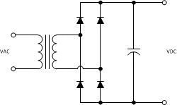
Full-Wave Bridge Rectified Supply
The full-wave bridge supply has a transformer with a single secondary winding, followed by four rectifying diodes in a bridge configuration. The secondary winding of the transformer is utilized in both half cycles, so the transformer can be smaller than with the full wave center tap rectifier. The capacitor only has to support the output current for one half cycle, and therefore the ripple is half as much as with the half-wave rectified supply. This circuit is suitable for higher power levels than the half-wave rectifier and has has the advantage of simplicity. However, it has two diode voltage drops to the output and twice the diode dissipation loss.
Full-Wave Bridge Rectified Supply
Advantages of Unregulated Power Supplies
The advantages of the unregulated supply are low cost and simplicity. There are many applications with do not require precise output voltage. Additionally, one can say that any linear power supply energized off the utility line has an unregulated supply on the front end followed by a regulator.
Disadvantages of Unregulated Power Supplies
Disadvantages of an unregulated power supply are as follows:
1. If the line voltage increases or decreases, the output voltage will increase or decrease.
2. As the load current increases or decreases, the output voltage will decrease or increase respectively due to the finite output impedance of the supply caused by transformer winding resistance, inductance, trace resistance, etc.
Analysis of Unregulated Power Supplies
Simple thumb rules can be applied to determine approximate design values. However, if more detailed and accurate analysis is required, it is best to employ electric circuit simulation techniques as the mathematical analysis is actually quite complex.
Next Topic
The next tutorial installment is: Linear Power Supplies. This next topic will answer the following questions:
- What is a linear power supply?
- How do linear regulators control the output variable?
- What are the performance and physical characteristics of linear power supplies?
If you need assistance with power electronics design, call or email us today for help with your requirements. You can also go to our power electronics consultant website for more information about our services for business clients. Thank you for reading this tutorial article entitled “Unregulated Power Supplies”
Next topic: Linear Power Supplies
Back to table of contents.


